Midwest-Capable RAK Unify 150 Node Build
Materials & Supplies
- RAK Meshtastic Starter Kit
- RAK Unify 150 Solar Enclosure
- We recommend the “with mounting plate and blank screw boss” and “with solar panel” options.
- See “Other Notes”
- 915mhz antenna (N or SMA)
- Corresponding IPEX to N or SMA bulkhead
- See “Other Notes”
- Vent plug (optional)
- Over/under voltage cutoff (optional)
- JST 2.0 connectors and wires
- Heat shrink tubing
- (3) 21700 or (5) 18650 Lithium Ion batteries (matching specs on all cells)
- See “Other Notes”
- Nickel strips, battery spot welder, soldering Iron, solder
- Or copper conductive tape
- Electrical tape or kapton tape/film
- Hot Glue
- M3 Screws
- Silicone (outdoor/UV rated)
Typical cost: $99-125
Build time: 60min
There are several RAK 150 node build videos and guides available on YouTube and other Meshtastic group websites, but none that we have seen accommodate for the extreme weather and solar conditions regularly encountered by MSP Mesh. Extremely low temperatures and very short solar daylight in the winter months have caused the node builders of MSP Mesh to take pieces from existing proven builds and add a few tweaks along with some of our own inventions to make the already versatile and excellent RAK Unify enclosure system even better for ANY climate.
Without further ado, here are the steps, start to finish, to build an MSP Mesh-capable RAK Unify 150 solar node.
Install the vent. Preferably drilled and facing downward to avoid water ingress. Alternatively you can drill one or two small (1/8″ max) holes at the bottom of the enclosure to allow the case to breathe and/or drain. If drilling instead of adding a pre-made vent, ensure the holes are small enough so that insects such as bees and spiders cannot enter. Make note of where the batteries will position in your build, and place the vent or vent holes in whatever available void you will have.
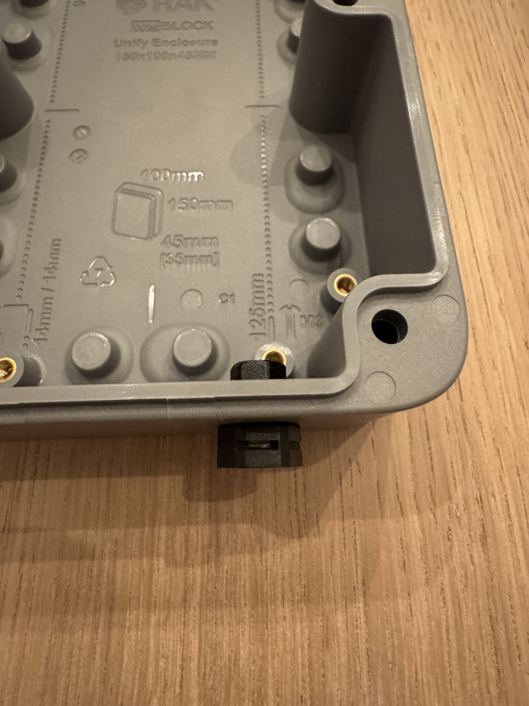
Drill the antenna bulkhead hole. Type N is 5/8″, SMA is 1/4″. Make sure if drilling a 5/8″ hole you place it with enough room for the bulkhead to be seated internally, avoiding the little “pegs” that stick up from the flat bottom surface. The spacing in the photo is adequate to avoid that issue.
For drilling N-type, be aware that the walls of the enclosure are relatively thick and some stepper-type drill bits will actually start cutting the next-size larger hole on the outside before completing the desired hole size. Unless you know that your stepper bit’s step surfaces are deep enough to make it all the way through the thickness of the wall, start with a normal 1/4″ drill bit and then use progressively larger bits until you reach the full 5/8″ diameter. If you end up drilling a hole that allows the N bulkhead to be installed, but has a larger diameter on the outside than the interior, don’t worry – it’s probably OK, and you will mitigate potential water ingress with silicone later in the build as well.

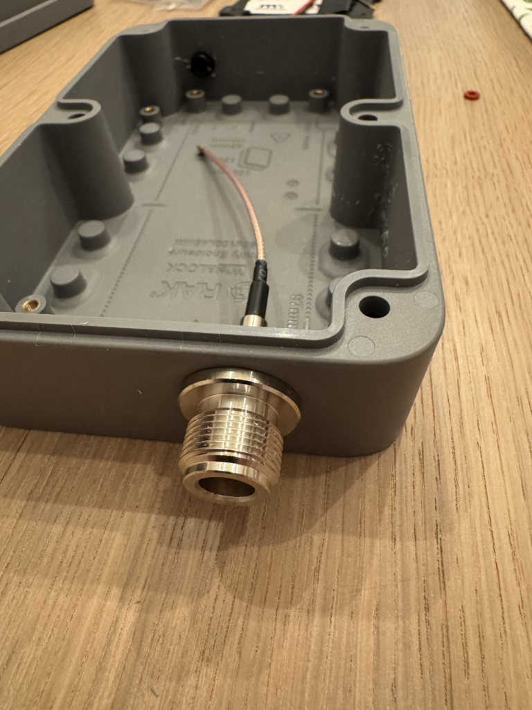
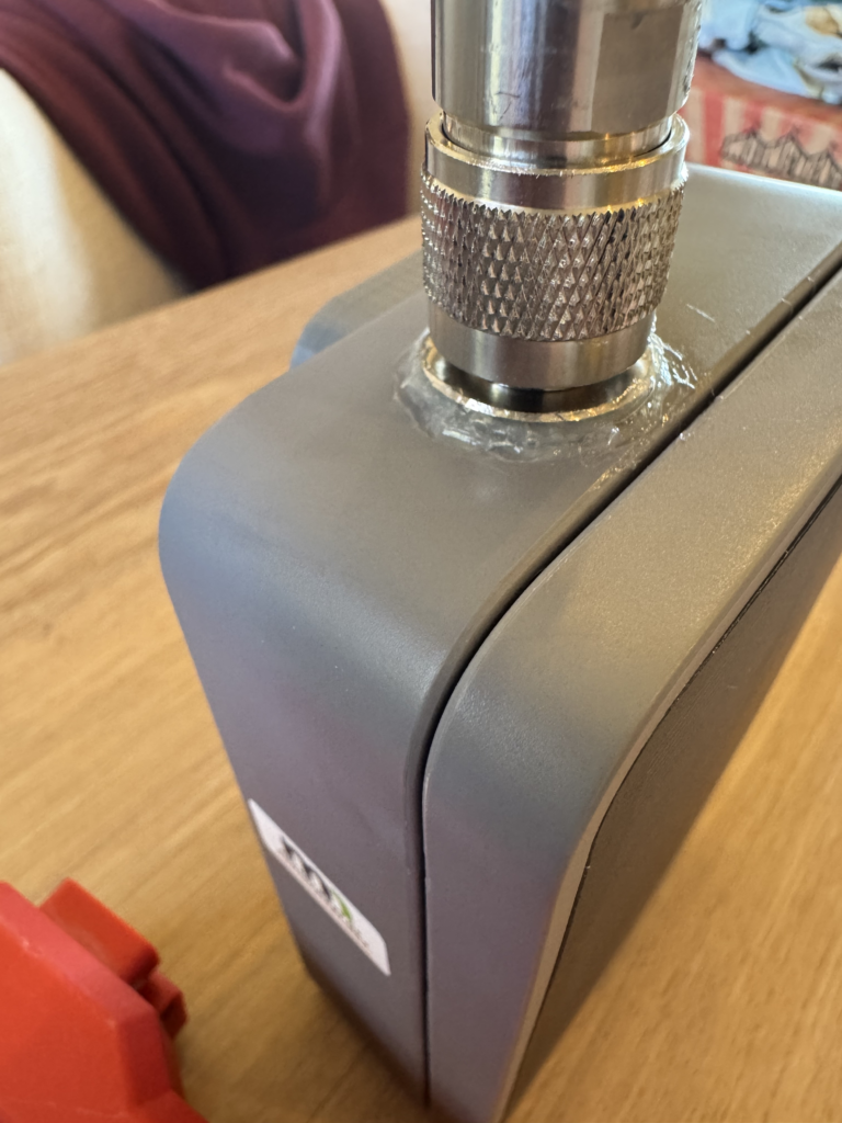
Antenna connector installation. There are several different designs of N-type bulkheads. Some have a rubber o-ring on the interior side, and the compressing bolt and washers go on the outside of the enclosure. The one pictured in this build is the opposite. This will vary by manufacturer and purchase source. Tighten with an appropriate wrench or small pliers and test tightness by attaching an antenna to its full installation thread depth, making sure that you cannot inadvertently rotate the bulkhead after the antenna is fully seated. Different antennas will have different amounts of thread visible while fully seated.
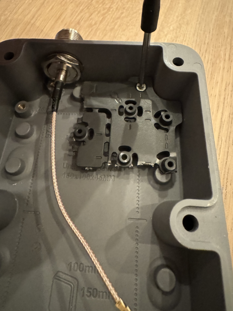
Cut the interior mounting board to size. You really don’t need much of the mounting plate to secure the main node hardware in place. Using the entire board will limit the amount of space you have for batteries, the bulkhead, and other equipment and doesn’t provide much if any benefit to the node.
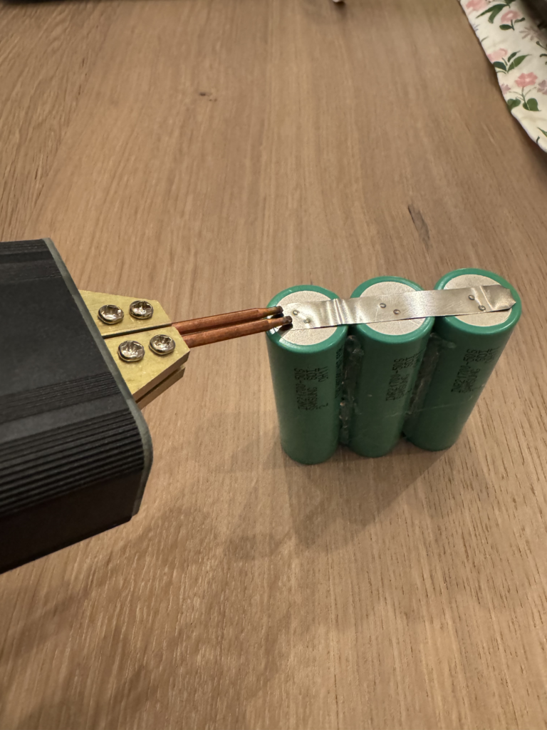
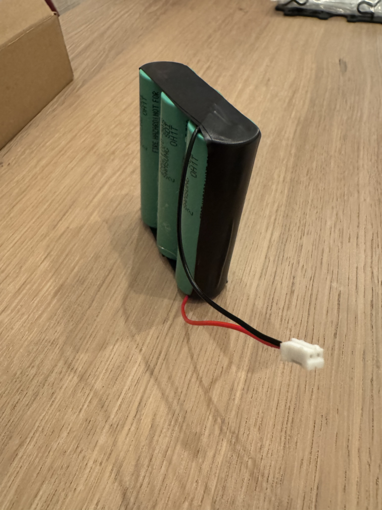
Construct a parallel battery pack using 3 21700 cells. Preferably use quality 5,000mAh cells with a high Amp rating to mitigate voltage drop in extreme climates . An alternative battery setup is to stack – 5 18650 cells of at least 3,000mAh in a slightly staggered 3×2 pyramid-stack configuration. Use hot glue to secure the cells to each other. The 18650 configuration may require that you position the batteries inside the node and glue them together one by one, testing to make sure the pack will fit, and that the lid will still close. NOTE: There is a small amount (about 3mm) of wiggle room above the lip of the enclosure before the batteries interfere with the lid closing.
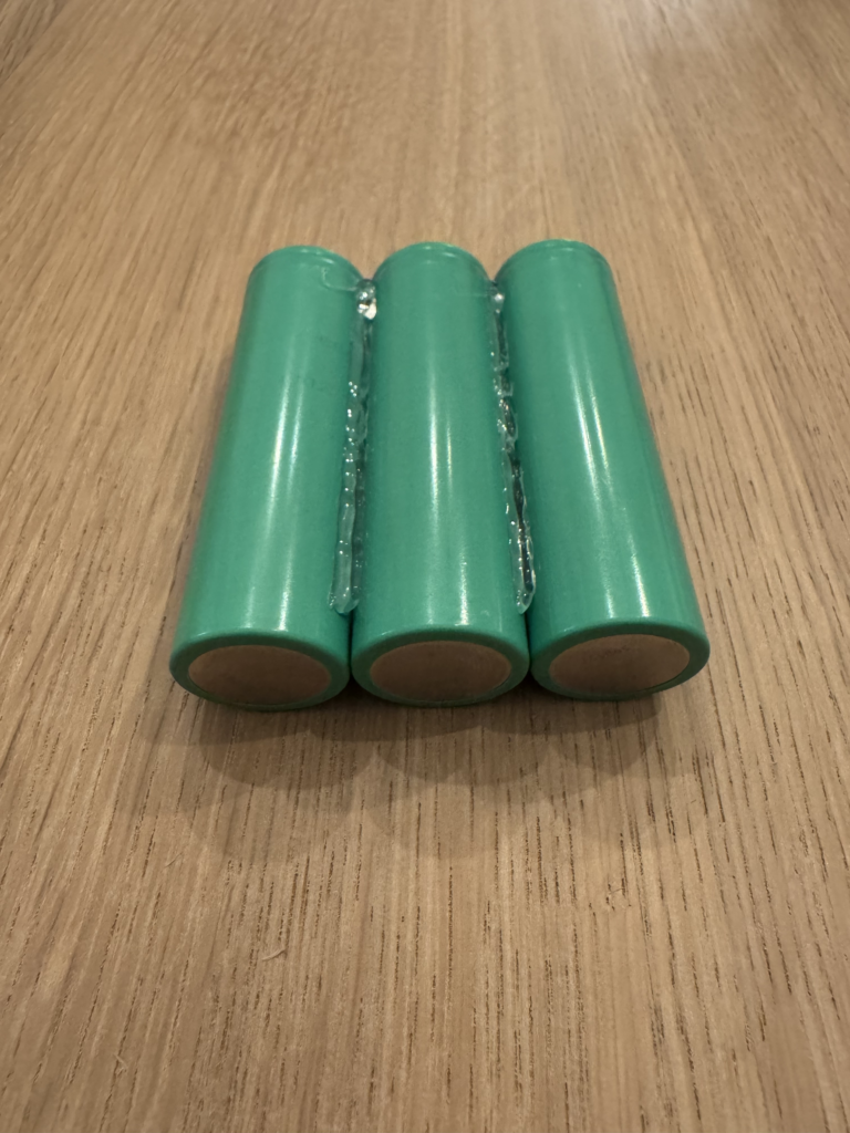
Spot weld in parallel with nickel strip. One strip for the positive connections, one strip for the negative connections.
Solder the JST 2.0 connector wires to positive and negative ends.
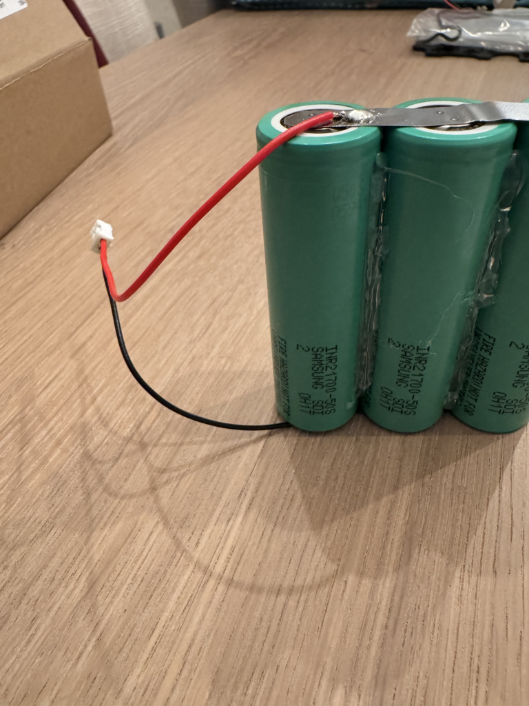
Wrap the exposed connections with electrical tape or kapton tape/film.
Connect to over/under voltage board. ALWAYS confirm polarity is correct before plugging in any of these things. Incorrect Red wire to the positive terminals. Voltaic Enclosures’ Etsy shop has the option to include pre-made cables with its battery protection modules, and to date, they have all been correct polarity and configuration. We recommend getting the cables with the modules.
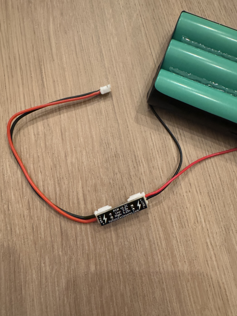
Wrap and secure the module in its supplied heat shrink tubing to secure connections. This can be done quickly with a lighter or heat gun. If you intend to be able to disconnect the wires from either side of the module, cut the heat shrink to the same length as the PCB itself.
Mount the RAK starter kit (4631 module) in the corner of the enclosure with the mounting board attached. Insert the battery pack as shown, or however your wiring will allow without interfering with the gasket lip. A 21700 battery pack will fit diagonally as shown, 18650-based packs may need to be arranged a different way, usually perpendicular to the antenna bulkhead.
Fully connect the main antenna to the antenna bulkhead and and then connect the two antenna IPEX cables to their properly labeled IPEX ports (“LoRA” and “BLE”) on the main node board before providing power to the board.
Before plugging in the solar panel and closing the lid, be sure to gently and evenly install the silicone gasket into the channel of the lid. Carefully use a small screwdriver, toothpick, or other narrrow, dull implement to ensure the gasket does twist or deform while being inserted to the channel. It is important that it lay flat all the way around, and is pressed fully into the channel every inch or so before allowing the lid to be placed up-side down for closing.
Finally, connect the solar 1.5 JST connector to the board. On both sets of JST cables, the RED wire should be oriented to the inside of the circuitboard, with the black negative wires oriented to the outside of it. Most RAK 4631 boards have a splotch of red paint on the inside-facing edge of each JST port to remind you of the polarity, since +/- are not printed on the PCB itself.
Now the inside is complete!
Secure the lid in a “star” pattern with the RAK-supplied screws (the largest ones in the packet, there should be 6 of them). The screws can be a bit of a pain, as they are not magnetic-enough for most small screwdrivers, and love to fall into the holes up-side down. We recommend using a precision screwdriver with a long thin neck so that screws can be manipulated more easily if they have fallen the wrong direction into the cavity.
Start by gently tightening the screws (start with opposite corners, move to the middle screws) less-than-completely, and when all 6 are in place, follow the same star pattern until each are just above finger-tight. There is no need to over-tighten these screws, as it only increases the chance that the silicone gasket will get pinched and create a chance for water ingress.
Apply outdoor-rated silicone with a small hand tool, cotton swab, fingers, etc (wash hands thoroughly afterward) to waterproof antenna bulkhead connection. By design N bulkheads should be waterproof, but it’s much better to be safe than sorry. Most RAK150 builds have the antenna mounted at the top of the node, so there is more risk of water penetrating and punishing tiny mistakes in drilling or a failed O-ring, etc.
If applicable for your deployment, mount the appropriate backer system with M3 screws. There are hose clamp, hanger, screw-in, and magnet mounts made by RAK.
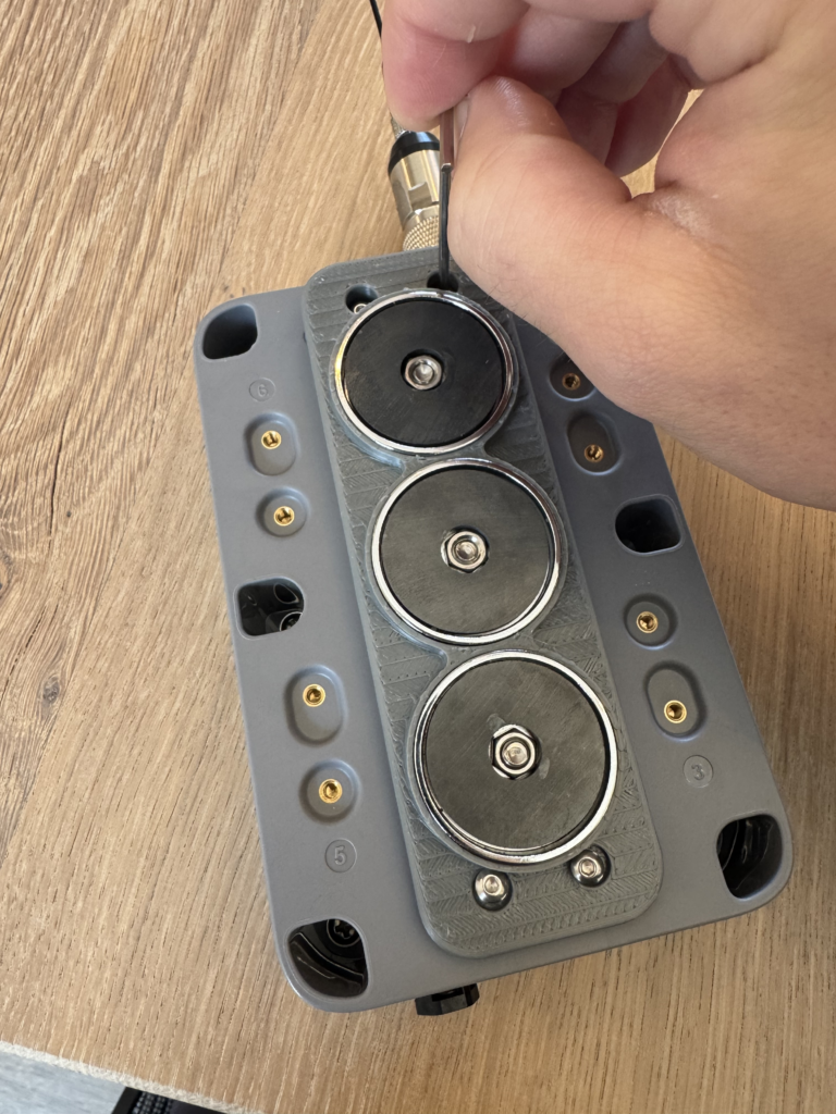
Admiring your handiwork at many points of the build, you might notice that the antenna is not parallel to the back of the enclosure by several degrees. This is a small but notable downside of the RAK Unify series. At MSPMesh we have designed and created purpose-specific 3D printed backer plates that correct the antenna angle, becoming perpendicular to the ground as well as addressing some of the limitations of many of the RAK-produced mounting solutions.
At time of writing there plans are available for 3D printed angle-correcting backer plates for magnets (as shown in this build) and for wall/screw mounting. Our experience in the wild is that the small downward angle that the solar panel must assume in order to correct the angle of the antenna is not noticeably detrimental to solar performance, even in Minnesota winters with very short daylight.
As long as your node is facing southward and not shaded from the light by trees or other obstacles a properly built 15,000mAh RAK150 node is equipped to survive 24/7/365 in all North American climates.
Other Notes
- Avoid batteries that claim uncommonly high mAh specifications. There is no such thing as an affordable, quality 18650 cell that has more than 3500mAh, and similarly no 21700’s higher than 5000mAh that are worth buying.
- Only buy batteries from respected, vetted sources that can guarantee authenticity.
Good battery sources include:- IMR Batteries
- Rokland
- Battery Hookup
- QUESTIONABLE BATTERY SOURCES:
- Amazon
- eBay (unless a trusted brand’s selling account)
- AliExpress
- Temu
- Similar advice for antennas. There are some gems in the wild from various sources but even those can be of questionable Quality Control.
Good antenna sources include:- DigiKey
- Mouser
- Rokland
- Antenna Farm
- GigaParts
- QUESTIONABLE ANTENNA SOURCES:
- eBay (unless you really know what you’re doing)
- Amazon
- AliExpress
- Temu
- Rokland does sell RAK Unify 150 enclosures, but at time of publication, they do not sell the variant we use. They carry a more expensive version that has an RP-SMA bulkhead built-in, as well as a weatherproof USB port. We have decided that while a good value with Rokland’s free/fast shipping, this variant is generally not worth the extra $19 per enclosure for our specific build style as it limits your choices of antenna, the USB interface is not commonly used (4-pin DIN) and takes up valuable internal space needed for batteries and other hardware.
NOTE: you do have to wait a while to get the enclosure directly from RAK (typically 10-15 business days) but the savings in build time internal space, and antenna options make it worthwhile in our judgement. - To keep your batteries from being able to shake/move around slightly you can adhere strip(s) of thin foam on top of the battery pack to help snug the top of the batteries that comes into contact with the underside of the lid.